Digital Logic
Circuit Logic Simulator
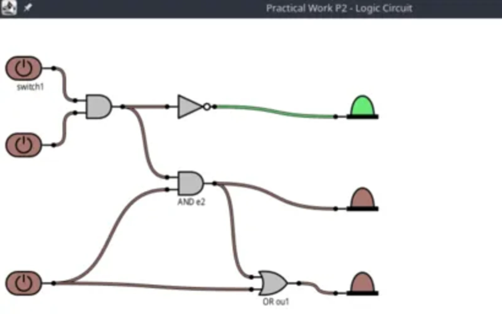
Showcase of the Circuit Logic Simulator project
Overview
The Circuit Logic Simulator allows users to create, modify, and analyze digital logic circuits. It provides several commands for validating circuits, generating truth tables, and animating circuit behavior.
Main Features
Circuit Validation
The VALIDATE command checks your circuit for:
- Cycles (logic loops)
- Isolated components (without inputs or outputs)
- Other potential issues
Truth Table Generation
The TRUTHTABLE command automatically:
- Identifies all Switch inputs
- Identifies all LED outputs
- Calculates output states for each input combination
- Displays or saves results
Circuit Animation
The ANIMATE command:
- Cycles through all possible input combinations
- Updates the circuit state
- Visually displays the results with a configurable delay
Basic Commands
Adding Components
Add various logic gates:
ADD g1:AND@100,100 "AND Gate";
ADD g2:OR@200,100 "OR Gate";
ADD g3:NOT@300,100 "NOT Gate";
ADD g4:NAND@400,100 "NAND Gate";
ADD g5:NOR@500,100 "NOR Gate";
ADD g6:XOR@600,100 "XOR Gate";
Moving Components
Move components to new positions:
MOVE g1 150,150;Removing Components
Remove unwanted components:
REMOVE g2;Listing Components
View all components in your circuit:
LIST;Or save the list to a file:
LIST components.txt;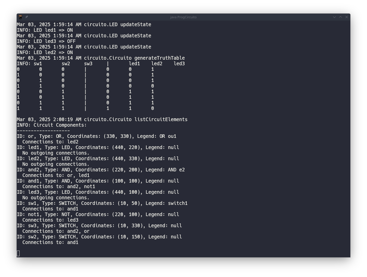
Advanced Features
Circuit Validation Example
VALIDATE;This will report any issues with your circuit, such as:
- Logic loops that might cause oscillation
- Components with no connections
- Incomplete circuits
Truth Table Generation
Generate and display a truth table:
TRUTHTABLE;Save the table to a file:
TRUTHTABLE results.txt;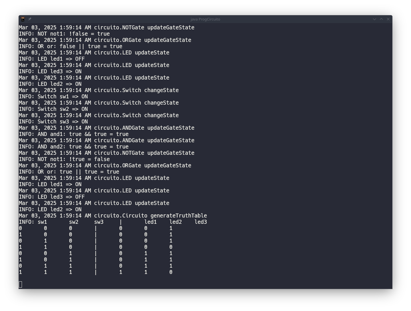
Circuit Animation
Animate with default delay (500ms):
ANIMATE;Animate with custom delay (1 second):
ANIMATE 1000;
Example Circuit
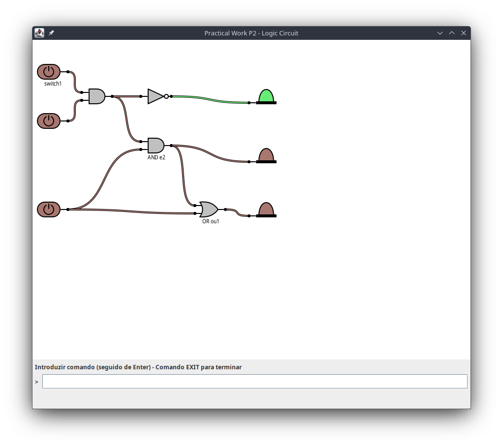
Here’s an example of a simple circuit created with the simulator:
Tips and Best Practices
- Always validate your circuit before generating truth tables or animations
- Use meaningful component names for better readability
- Position components in a logical flow (inputs on left, outputs on right)
- Save complex circuits to files for future reference
Conclusion
The Circuit Logic Simulator provides powerful tools for digital circuit design and analysis. Use the commands outlined in this guide to create, validate, and test your digital logic designs.